Parallel Input Serial Output Shift Register Verilog Code
Joy Division were an English rock band formed in 1976 in Salford, Greater Manchester. Joy division unknown pleasures shirt. The remaining members reformed as New Order and they have gone on to achieve much critical and commercial success. The band dissolved in May 1980 after the suicide of its lead singer, Ian Curtis. • • Albums:,,,,. Much of their popularity/reputation arguably resulted from frequent playings on air by iconic DJ John Peel, but it is easy now to overlook the impact that the first album, Unknown Pleasures, had on post-punk music at the time, as reference the number of prominent bands that cited this album as an influence.
Chutti tv all programs list. The show ended after 26 episodes on 23 September 2017. The show had parents and their children (ages 2-3) as the participants.
Re: verilog code for serial in parallel out shift register I am not checking your code! I want to give the input in code itself.I don't want to use testbench to give different serial inputs. 4 Bit Comparator Design Verilog CODE. Serial OUT Shift Register using Behavior Modeling Style. Parallel IN - Serial OUT Shift Register.v.

Serial Input Serial Output Shift Register

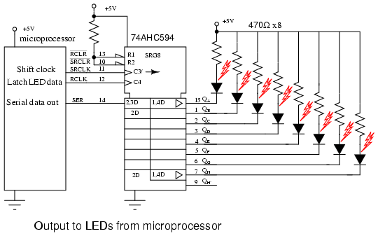
Parallel Input Serial Output Shift Registers
Introduction The shift registers store a value and shifts it. They are extremely useful. They are used to convert information from parallel to serial (and vice versa) for use in syncronous communications. Communications through SPI, I2C, and more are implemented with these registers. The also allow us to perform the operations of multiplying by powers of 2 and dividing by powers of 2 for integers.
In this chapter we will use them to generate a sequence of 4 states on the LEDs of the iCEstick, moving the lights clockwise. Description of the register. The shift register we will use is as follows: The output of the register is N bits (in our example we will use a 4 bit register). It has an N-bit Parallel input, which allows us to load the register with a new value. The load_shift signal allows us to determine the operating mode: when it is at 0, a new value is loaded when a rising edge of the clock arrives. When it is at 1, a right shift is made on the rising edge of the clock. In this shift the most significant bit is lost and the new value is read from the serin input (serial input).
Most Viewed Articles
- Horizon In The Middle Of Nowhere Episode 1 English Dub
- Intel Desktop Board 21 B6 E1 E2 Driver
- Kertas Kerja Program Inklusif Pendidikan Khas
- Free Download Film Semi 3gp Subtitle Indonesia
- Install Igo8 On Mio C320 Unlock
- Total Overdose Full Save Game Files
- Download Emperor Battle For Dune Resolution Patch
- Franz Schubert Torrent Complete
- Descargar Formato Hoja De Vida Minerva 1003 En Word Gratis
- Contoh Proposal Program Kreativitas Mahasiswa Gagasan Tertulis
- Toushin Toshi 3 English Patch
- Serial Email Extractor 5.6.1.0
- Samehadaku Naruto Shippuden Eps 330
- Aunty Kathalu Telugu Pdf
- Sketchup Pro 2013 Crack Serial
- Heimdall One Click Unbrick Download
- Hrd Version 5.24.38 Download
- Microsoft Developer Studio Fortran Powerstation Download
- Download Buku Dale Carnegie Bahasa Indonesia Pdf
- Contoh Program Vb Dengan Database Mysql


